mirror of
https://github.com/netz39/www.netz39.de.git
synced 2025-01-19 04:20:10 +01:00
99 lines
No EOL
12 KiB
Markdown
99 lines
No EOL
12 KiB
Markdown
---
|
||
author: lespocky
|
||
layout: post
|
||
title: "Nitpicking on the adafruit USBtinyISP"
|
||
date: "2014-05-18"
|
||
categories:
|
||
- "laufende-projekte"
|
||
tags:
|
||
- "eagle"
|
||
- "rant"
|
||
- "usbtinyisp"
|
||
feature-img: "https://cdn.netz39.de/img/post-img/2014/usbtiny_rant_brd_orig-1280x486.png"
|
||
thumbnail: "https://cdn.netz39.de/img/post-img/2014/usbtiny_rant_brd_orig-1280x486.png"
|
||
---
|
||
|
||
We had some visitors from the U.S.A. for a great [soldering workshop](https://www.netz39.de/2014/loten-im-mai-ein-workshop-fur-anfanger-und-fortgeschrittene/ "Löten im Mai – Ein Workshop für Anfänger und Fortgeschrittene") yesterday last week. While [Jimmie P. Rodgers](http://jimmieprodgers.com/) and [Mitch Altman](https://twitter.com/maltman23) were showing the kits they brought to solder, they also showed the [USBtinyISP AVR Programmer](https://learn.adafruit.com/usbtinyisp) by adafruit, and I couldn't resist ranting about it. This blog post is elaborating on this rant and share what I found out, but let's start from the beginning.
|
||
|
||
At the OHM2013 camp I had a workshop [AVR 101](https://program.ohm2013.org/event/242.html) and being badly prepared I [bought three](https://twitter.com/LeSpocky/status/362674275133562881) of those programmers at the camp from Mitch for my workshop. Soldering them was not too hard, and we successfully used them for the workshop.
|
||
|
||
Being back home I started working on the next parts of what will eventually be a course for teaching AVR programming and after the first successful rerun of the first part of the course at our hackerspace I thought we need more programmers. I liked the idea of the USBtinyISP for being an open device with an AVR microcontroller on it you can build on your own, but adafruit kits are not that easy to get in Germany and I don't want to order things from overseas I can do here on my own anyway. The USBtinyISP is under a Creative Commons share alike license, so I got the Eagle files and started designing my own board for etching in our space based on the adafruit one. I stumbled across some issues in the original design. This is were the rant starts.
|
||
|
||
**Disclaimer:** adafruit does great stuff. This is not meant as offense, but as nitpicking from a perfectionist's point of view by an engineer in mechatronics who uses Eagle at work and for hobby. Maybe you learn things about Eagle you didn't know und get some inspiration for your own design decisions.
|
||
|
||
## Schematics
|
||
|
||
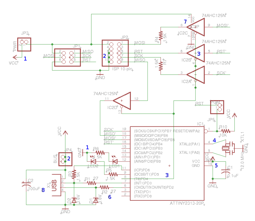
First we have a look on the schematic:
|
||
|
||
|  |
|
||
|:--:|
|
||
| Eagle Schematic USBtinyISP by adafruit |
|
||
|
||
I made some blue numbers, there's one real mistake they made, this is number 6: the values of the series resistors R1 and R2 for USB. The ATtiny 2313 is running a software USB stack which is probably [V-USB](http://www.obdev.at/products/vusb/). According to their recommendations you should use 68 Ohm instead of the 27 Ohm in this schematic. What you see in the schematic at those resistors is the value was moved around. You can do this with Eagle to place it somewhere else, however I usually leave it at the default place and increase the distance between the parts in the schematic if I want to have them well readable. ((To move name or value away from a part you call _smash_ on the part and then move those labels. To have them back at the default positions call _unsmash_.)) Next thing, still with number 6, but also with most other parts is how the value is written. There are some non written rules in electrical engineering how to do this. The advantage of following those rules is making it easier for other engineers to read your schematics, keep it short, and avoid ambiguity. Decimal points for example tend to be unreadable in small or old or bad prints or prints on the circuit board. In case of resistors, you do it like this:
|
||
|
||
| value | in schematics |
|
||
| --- | --- |
|
||
| 1,5 Ohm | 1R5 |
|
||
| 15 Ohm | 15R |
|
||
| 1,5 kOhm | 1k5 |
|
||
| 15 kOhm | 15k |
|
||
|
||
The decimal point is replaced by the unit prefix or an uppercase R if there's none. If there's no decimal point because there's no fraction part, it's appended. The unit itself is not written, because it's clear what unit the value of a resistor has. The same thing goes for capacitors, but there's another thing you can see near the blue 5: the value of C1 is written as 0.1uF, you could leave out the F, but I recommend to not use leading zeros and instead use the next smaller unit prefix, so for C1 you would write 100n as value.
|
||
|
||
Speaking of 5 we can talk about both blue 1 now: I always find it nice, if the GND connectors are in the lower area of the schematics or at least below the parts they are connected to. Same goes for VCC which would be somewhere above. I would not rotate them to the side, the do not look familiar then and it takes time for my brain parsing this instead of just knowing what it means. The other criticism I have is, in adafruit's those are very close to the parts, more hidden beneath the part than easy to spot.
|
||
|
||
On 5 you can see a problem which you have also on 2 and 4 and lot of other spots in this schematic. Parts have red lines with signals and you connect them with green wires. If you go straight away you can easily move your parts around later and all wires are nice vertical or horizontal. In case of 4 however we could also blame the one who made the ATtiny2313 package. You almost always want to connect capacitors and a crystal to XTAL1 and XTAL2. If those pins had a little more space in between them, you could go straight with your wires in the schematic.
|
||
|
||
What you also see on 2 and on numerous places in this schematic are superfluous junctions. You need junctions if you want to join crossing signals, however wire ending exactly on a pin automatically makes an electrical connection.
|
||
|
||
Another problem I have with 2 and also with 3 is crossing your parts with signals. Especially on 3 it's hard to spot if the triangle elements have a pin on top or not? Without knowing this 74AHC125 is a quad tristate buffer and it has only three pins per element, would have guessed? Crossing at 2 is almost as puzzling when you try to read it. You will see I made an exception on crossing the big microcontroller in my schematic, but that was a compromise out of laziness (yes I am too).
|
||
|
||
Left over are 7 and 8. With 7 this was probably due to laziness, the GND and VCC connectors of the 74ACH125 were not moved away from the device to be clearly to see. But what about 8? It's readable with enough space around. Here comes in a general rule of thumb you could have seen in all those descriptions above: make your schematic easily readable. This includes grouping things together which build logical units and in this case let the schematic help you following the signal flow. USB is the outside connector, signal comes in there, then is smoothed by the capacitor C2 and then goes through the resistors and into the ATtiny. Having the connector in between breaks up this signal flow making the circuit harder to read.
|
||
|
||
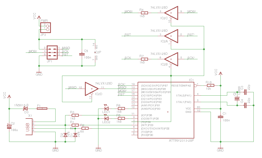
See my derived version of the circuit: [GitHub](https://github.com/netz39/circuit_boards/tree/master/usbtinyisp)
|
||
|
||
|
||
|
||
I fixed all the things I criticized above but what else?
|
||
|
||
- I obviously dropped the 10-pin ISP header, we design our circuits with 6 pin headers only and in case you can make another cable instead of wasting board space.
|
||
- I added a Schottky diode and a fuse for USB port protection. Since the target can be powered by this or by itself and those parts are cheap, why not protect your USB port?
|
||
- I mirrored one of the four buffers to help understand signal flow (three go out from to uC to the target, one goes from the target to the uC)
|
||
- I added a 100n capacitor near the 74AHC125. As a rule of thumb you add 100n capacitors near the GND and VCC pins of all integrated circuits.
|
||
- I removed JP5 which seemed to be a relict from a previous board revision. It's not populated on the final USBtinyISP anyway.
|
||
- I removed JP4 which does not even connect or disconnect anything. It distracts you in the schematic and makes you board more complex for nothing. Investigate it, it makes no sense at all!
|
||
- Oh and I replaced all U.S. parts with European parts, not because of some kind of patriotism, but because I wanted to order my parts here at [Reichelt elektronik](https://secure.reichelt.de/), where we order most of our parts.
|
||
|
||
## Board
|
||
|
||
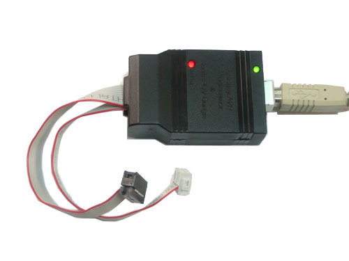
The original adafruit USBtinyISP is a double layer board, so for making a single layer one, I had to change it anyway. So what where my design decisions and what did I discover on the original board?
|
||
|
||
|  |
|
||
|:--:|
|
||
| the original USBtinyISP |
|
||
|
||
|  |
|
||
|:--:|
|
||
| original board with annotations |
|
||
|
||
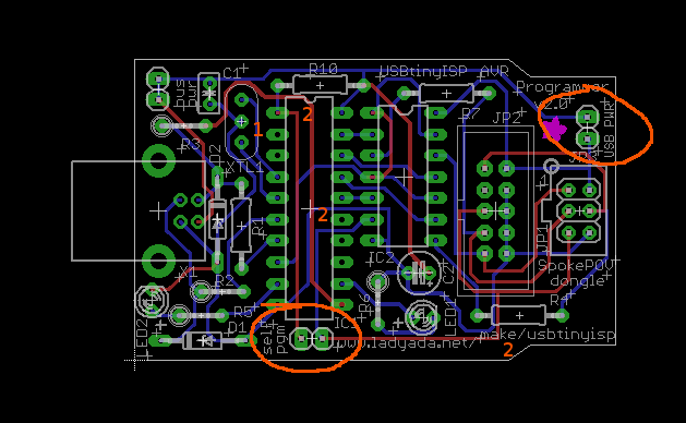
First thing I noticed: there are jumpers on the layout which are not accessible in the black case you get with the device. Those are the ones in the orange circles and those are the already mentioned JP4 and JP5. (You have to turn one of the pictures above 180° in your head to spot this.)
|
||
|
||
Then there's no ground plane. You do not need one if you give your board away for producing, but if you're etching yourself you want to etch only the real necessary stuff to save chemicals and produce less waste with nasty copper ions.
|
||
|
||
Another thing are the resistors: R2, R3, R5, and R6 stand upright. You can do this, I don't like it. R7 is placed to close to IC2 so you have to bend it and it's not on its silk screen print. You could use resistors with less electrical power ratings if you don't use the 27 Ohm ones. If you use the 27 Ohm ones: metal film resistors in 0207 size have a 0.6W rating compared to 0.25W for carbon film resistors, saving space compared to carbon film resistors with a suitable power rating. 0.33W is approximately needed for 27 Ohm series resistors, but only 0.15W for 68 Ohm. However in my design those are still non-SMD resistors and we use metal film resistors here, so with 68 Ohm metal film resistors in the new design we are on the safe side.
|
||
|
||
So there are some annotation numbers left in the picture of the board. Near 1 is a part I never saw in Europe, it's a crystal with integrated capacitors, which I replaced with a usual crystal and separate capacitors. Near 2 there are 90° angles in the traces on the board. They are not critical in this design, but we want to etch by ourselves and there's another point. If you have a choice between two things in one case and on a similar topic you don't have the choice and must use one of them, I prefer to always use the choice which always works if it has no disadvantages in the first case. Speaking of trace angles: it doesn't hurt to avoid 90° angles in all designs and if I don't do them anyway I get a better design from start in the case I need them. For a discussion on the traces topic, see the comments at [Dangerous Prototypes](http://dangerousprototypes.com/2012/12/31/why-right-angle-bends-on-a-pcb-are-not-so-bad/).
|
||
|
||
**Update:** And I forgot something, when I first published this post. There are lots of additional labels for the silk screen. This is not necessary. They could have used the _smash_ command in Eagle like they did in the schematics and place the labels where they want instead of hiding this layer and adding tons of new labels on another layer.
|
||
|
||
So see my new board:
|
||
|
||
| 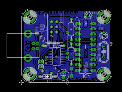 |
|
||
|:--:|
|
||
| new usbtinyisp by alex |
|
||
|
||
You notice there are SMD parts, but with the right tutorial soldering a 0805 package is not that difficult. The board size is 36mm × 44mm, so it's not compatible to [Sick of Beige compatible cases](http://dangerousprototypes.com/docs/Sick_of_Beige_compatible_cases), but at least the screws have the same distances from the corners. ;-)
|
||
|
||
## Comments
|
||
|
||
If you want to comment on this, feel free to do so right here. You can also fork the project [on GitHub](https://github.com/netz39/circuit_boards), it's still CC licensed. :-) |